Circuitry
There is only a small bit of external circuitry required to make this setup work, and a schematic can be seen below:
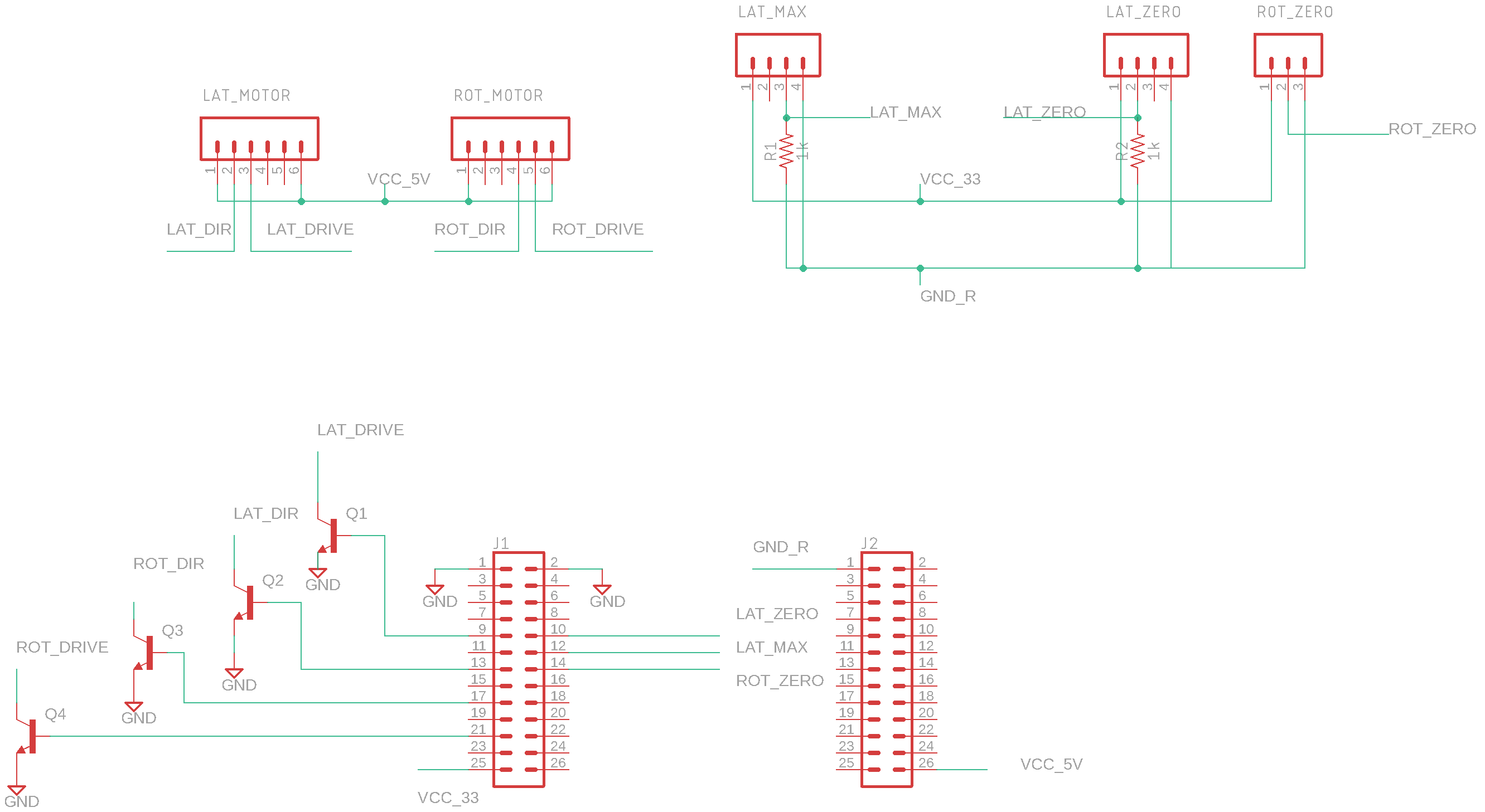
In order to facilitate ease of construction, the gerber files are available here or you can order copies directly from OSHPark here.
- This add-on board has a few purposes:
Power and receive signals from sensors
Send signals to motor controllers
Convert 3.3V logic levels to 5V outputs for motor controllers
A finished build is shown below:
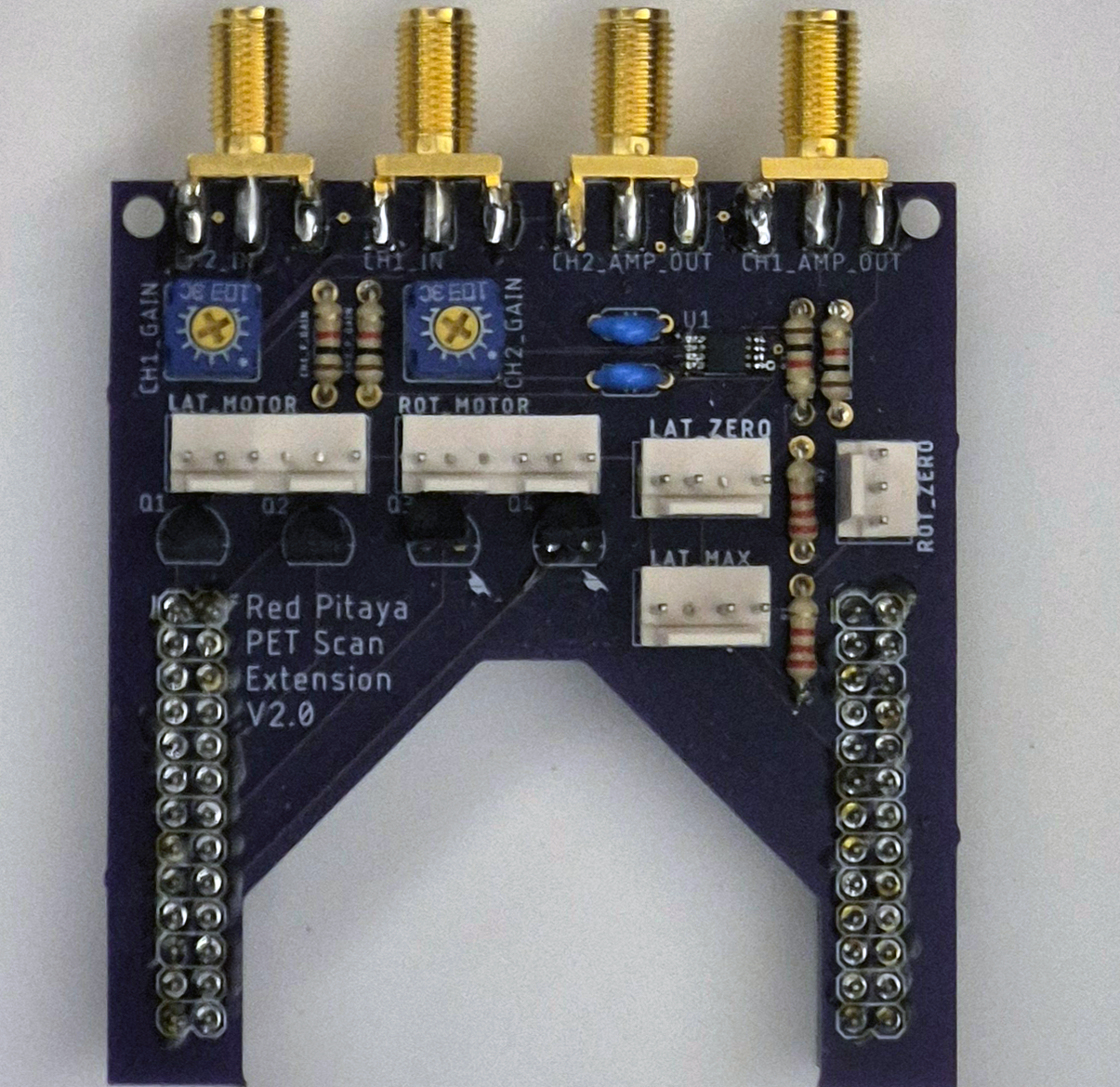
While it may be slightly difficult to see from this angle, four of the five JST headers have pins removed. This was intentional, as by removing those pins and filling the corresponding sockets with a solid material (hot glue is good as it can be removed if needed) it is possible to make cables that cannot be connected improperly without heroic effort. This makes the setup far more robust against assembly failures.
A board for a stand-alone HV power supply is available here
The finished board is shown below:
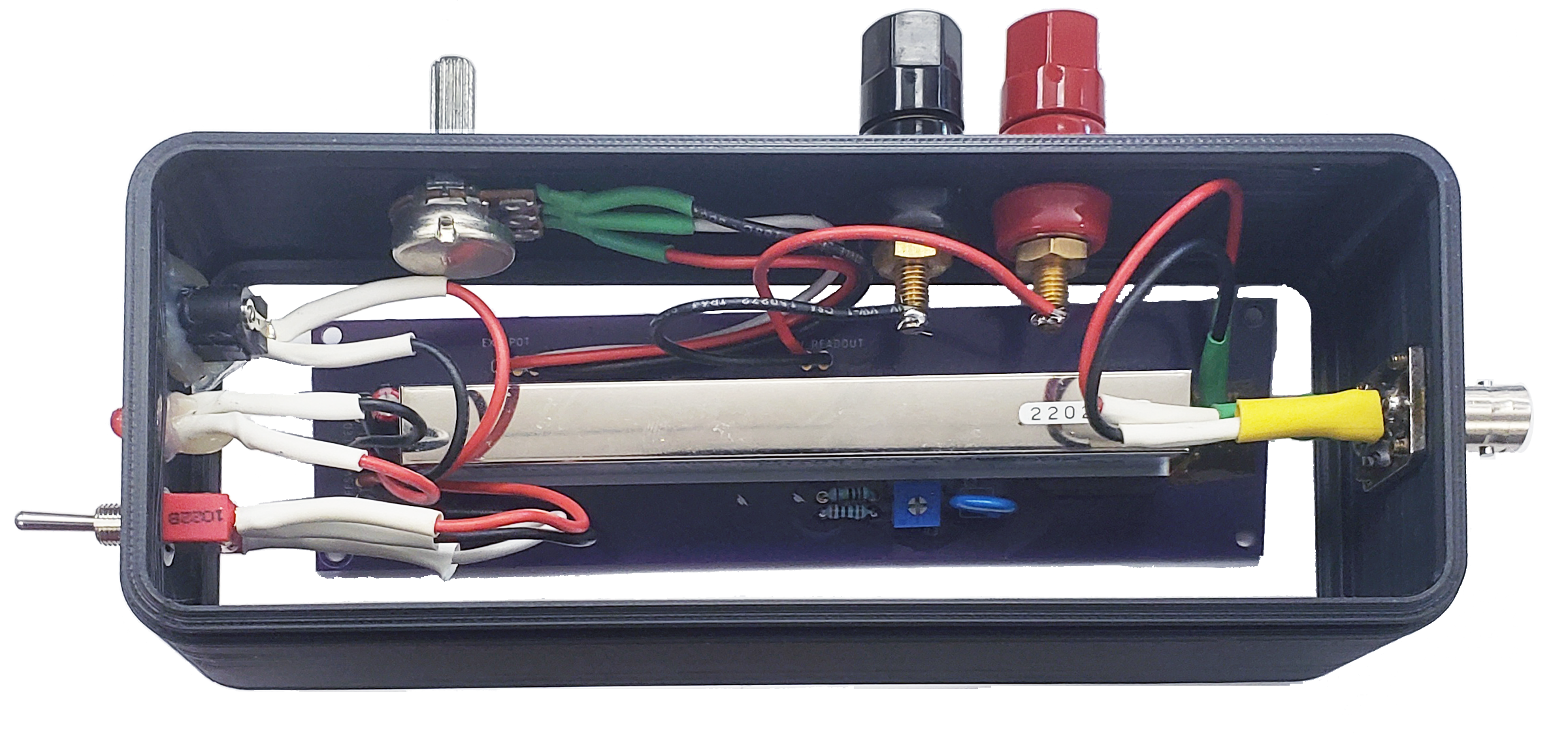
Note that most of the wiring here is 22AWG stranded core. The flexibility is useful as it makes strain-related failures less likely when the module is fitted into its enclosure. The potentiometer on the outside of the case is used for setting the voltage from ~0 to 1 kV. The internal potentiometer is used as a fine adjust after the device is first constructed and can be safely ignored later.